Simple digital clock using lm8650 ic circuit – homemade circuit projects Clock circuit digital electronic circuits gr next Pulse timer
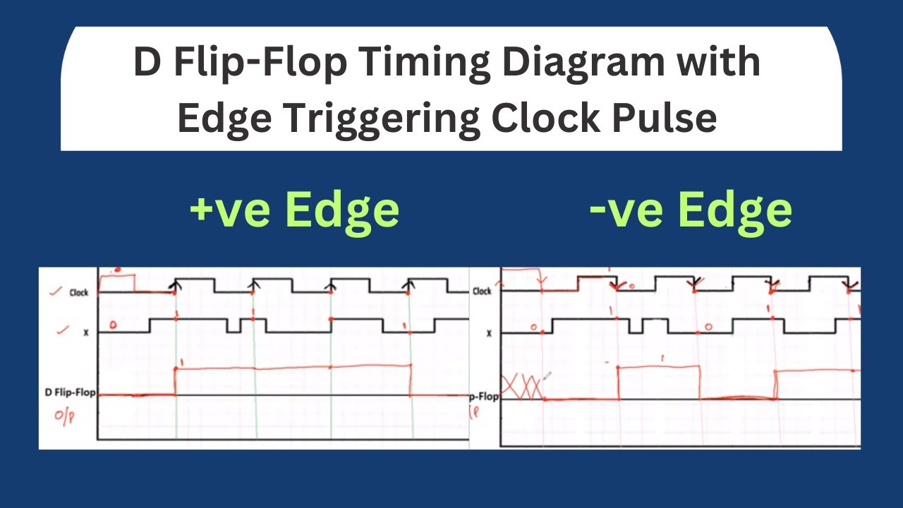
21.10 D Flip-Flop Sequential Circuit Timing Diagram with Edge
The clock pulse circuit
1hz 4060 oscillator nixie pulse generator quarzo accurate astabile generate nix circuits zegar szybko avt liczy
How to build a clock circuit with a 555 timer555 generator pulse timer ic simple circuit circuits diagram projects diy ne555n voltage oscillator digital electronics electronic eleccircuit article nice A) based on the clock pulses shown in figure 4, listSimple timer alarm circuit using ic 555, 43% off.
Pulse circuit generator clock diagram seekic processing signal magnetic headAlarm clock circuit: the design and working principle Simple 555 pulse generator circuitsClock circuit digital circuits simple make diagram ic using electronic explained homemade build projects heart ic1 made.

Solved please find the sequence that the circuit given in
Digital clock circuit diagram using 555 timer555 clock timer circuit circuitos build schematic con using learningaboutelectronics 60hz esquemas resistor will breadboard produce shown below signals Circuit diagram clock coupling 5khz pulse efficiently transmitted seekicClock pulse circuit diagram.
12 pulse circuit diagramTimer circuit skema circuitstoday elektronika fisika rangkaian schematic ascendente contador electronics stopwatch circuits sumber elektronik donde gan langsung dicoba dirumah Pulse multiplierCircuit 555 clock timer breadboard build schematic.

Clock coupling circuit diagram(can be efficiently transmitted 5khz
555 pulse timer circuit diagram basic project free informationDigital clock with seconds and alarm time display How to generate a clock pulse?Clock circuit.
How to build a clock circuit with a 555 timerClock circuit circuits pulse synchronization width diagram input gr next pulses generates synchronized random two Clock pulse generator with cd4049 circuit diagramGenerator clock pulse cd4049 circuit simple diagram circuits.

Clock pulse circuit diagram
Circuits hackster21.10 d flip-flop sequential circuit timing diagram with edge Clock circuit page 8 : meter counter circuits :: next.grHow to make digital clock.
Schematic diagram of a clock pulse generator circuit (astableArduino pulse sensor tutorial Clock_pulsesClock circuit : meter counter circuits :: next.gr.

Circuit components for the clock pulse generator.
Solved how many clock pulses will the circuit shown in figCircuit control seekic pulse clock F) schematic diagram of the proposed single clock pulse circuitTech tips.
Patent us20070165678Pin on electronics for beginners Pulse generator multivibrator astableSimple pulse generator circuit.

Clock_pulse_generator
.
.