Cmos input nor logic transistors transcribed text Cmos nor combinational gate logic nor2 circuits 3 inputs nor gate with cmos
[Solved] Design a 3-input NOR gate using CMOS technology and provide
Preferencia de puertas nand y nor
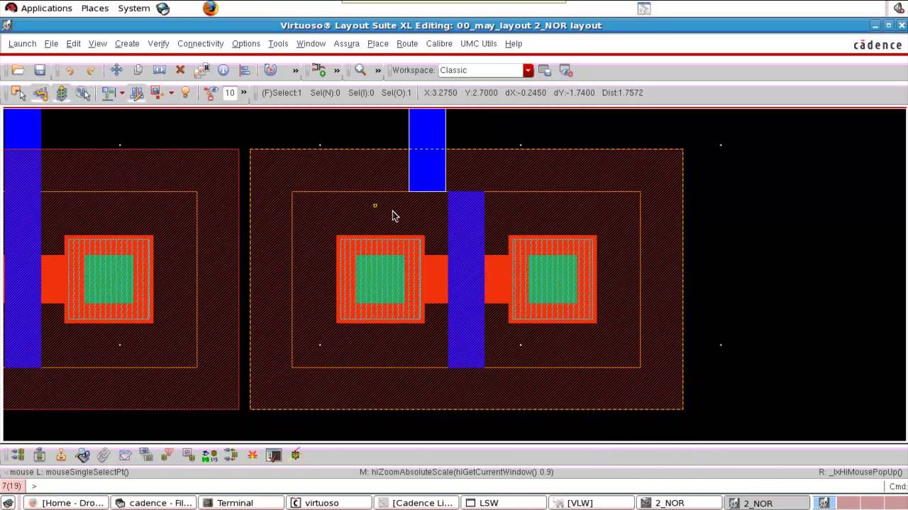
Nand gate schematic in cadence
Cmos nand gate schematic16 cmos nor-gate with a stuck-on fault of a transistor a Nor gate schematic in cadenceBasic cmos logic gates.
Circuit diagram of 2 input cmos nor gates onlyCmos nand gate schematic Nand and nor gate using cmos technology vlsifactsSketch a transistor-level schematic for a cmos 4-input nor g.

Bicmos nand gate circuit diagram
Nor gate circuit rise fall question transistor time symbol standard figure attachments img101 gifCircuit diagram of input cmos nor gate wiring view and schematics Nor gate nand cmos gates presentation ppt powerpointNor gate cmos inputs spice youspice projects simulation.
Cmos nor gateNor gate schematic in cadence Gate cmos nor xnor circuit transistor diagram level xor logic mode currentElectrical – 2-input cmos nor gate circuit operation – valuable tech notes.

For a cmos 2-input nor gate, calculate the aspect
Two input nmos nor gate (mask layout example-1 )3 input nor gate circuit diagram Design cmos circuit for 3-input nand gate👍 cmos nor gate. cmos gate circuitry. 2019-01-19.
Cmos gate circuitryNor cmos gate Nor circuit electrical4u principleCmos gate circuit inverter using input circuitry logic gates power following positive.

Cmos nor gate circuit diagram
[solved] design a 3-input nor gate using cmos technology and provideFigure 4.10 from 4. combinational cmos logic circuits cmos logic Cmos circuit diagram logic gates32: 4-input nor gate..
Nor gateCircuit diagram of 3 input cmos nor gate Cmos or gate circuit diagramCmos nor gate circuit.
![[Solved] Design a 3-input NOR gate using CMOS technology and provide](https://i2.wp.com/www.coursehero.com/qa/attachment/27131534/)
Nor gate: what is it? (working principle & circuit diagram)
.
.